I recently completed a calculator app challenge from Frontend Mentor. I enjoyed working on the challenge, so I decided to write about how I approached it (and thus, to launch this blog 😃). Frontend Mentor, by the way, is a website providing frontend developers with challenges to translate user interface (UI) designs into working code. The challenges vary in difficulty and can be completed using any web technologies.
My challenge was to create a basic arithmetic calculator, as in the following design. The challenge required CSS skills to match the layout and themes of the design, as well as JavaScript skills to make the calculator interactive. This article focuses on the interactivity part.
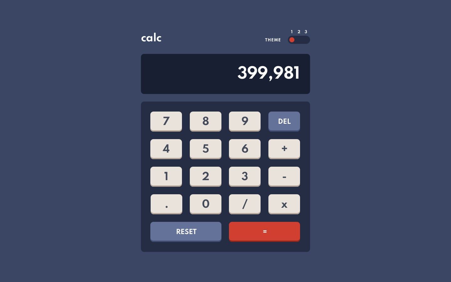
Making the calculator app interactive seemed straightforward at first glance. After all, there were only a handful of rules to follow:
- When a digit button, an operator button or the decimal point button is pressed, append the digit, operator or decimal point to what's on the calculator display. That is, when the buttons 2, +, 3, . and 4 are pressed in that order, append the expression
2 + 3.4to the display. - When the = button is pressed, solve the expression on the display, then replace the expression with the result.
- When the delete (DEL) button is pressed, remove the last character on the display.
- When the reset button is pressed, clear the display.
However, as I experimented with other similar calculator apps, I noticed they had some other important subtle behaviours. Below, I describe scenarios leading to some of these behaviours. I really suggest you open a calculator app at this point to reproduce the scenarios yourself. If you don't have a calculator app, you can use the Google Search calculator online.
- Scenario 1
- You clear the calculator display and press the buttons 2, +, 3, . and 4, resulting in
2 + 3.4on the display. You then press the buttons . and 5. If the calculator followed just the naive rules I listed above, it would append.5to the expression on the display, updating it to2 + 3.4.5. But this new expression would be invalid, because of the supposed number3.4.5, which contains two decimal points. A number can't have more than one decimal point, at least not in the mathematical notation we commonly use. Your calculator may instead ignore the decimal point but accept 5, so the display now shows2 + 3.45. - Scenario 2
- You clear the display and press the buttons 7, −, 4 and ×, so the display shows
7 − 4 ×. This expression is incomplete because there's no number after the×operator yet. Now you press the = button to solve. What's supposed to happen? It's likely your calculator ignores the = button. - Scenario 3
- You clear the display and press 1, +, 1 and =, so the display shows
2(the result of the expression1 + 1). Then you press 3. Your calculator may replace the previous result with the new digit, so that your display now shows just3. Again, if your calculator followed just the rules above, it would instead append3to the previous result, updating the display expression to23.
Your calculator may behave differently from what I described above, but you can probably still appreciate how carefully your calculator handles the scenarios.
There are more exceptional scenarios to consider, as we'll see later in this article. (Can you think of any?) To handle all the scenarios without ending up in a mess of if statements and what have you, I decided to model the calculator as a 'state machine' (I'll explain what this means soon). The resulting code was thorough, well-structured and easy to understand and extend.
This article describes the calculator state machine and demonstrates, in a small way, how to use a state machine in building a robust user interface. I want this article to be accessible to fellow developers who aren't very familiar with JavaScript, so I include many diagrams and short videos but only a few code snippets. After all, this article is about modelling, not coding.
You can check out the finished calculator app (to play with it 🙂) before reading on.
What is a state machine?
A state machine (or a finite-state machine) is an abstract model from computer science theory that's used to describe a system whose behaviour at any time depends on the previous inputs it received. Our calculator is one such system. For example, it ignores or accepts a decimal point depending on whether the last thing on its display is already a decimal.
For our purposes, a state machine consists of states, an initial state, events, transitions and actions:
- The states represent the different finite modes or conditions that determine the machine's behaviour. The machine exists in only one state at a time.
- The initial state is the state the machine starts in.
- The events are the inputs the machine can react to.
- The transitions are the changes in state the machine can make. The machine can transition from its current state to another state only when it receives an event.
- The actions are the instant side effects the machine can perform during a transition or when entering or exiting a state.
We can see a simple example of a state machine in turning on/off an air conditioner (AC). An AC starts in an off state and goes to an on state when its power button is pressed. It also beeps during that transition. When the button is pressed again, the AC returns to the on state and beeps once more. The AC is always either in the off or on state (but never both) and changes state only when the power button is pressed.
We can visualise this AC machine as the following state diagram:
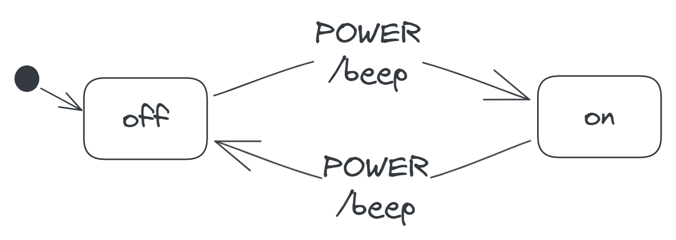
The rounded rectangles labelled off and on represent the states, while the arrows leaving and entering the rectangles represent the transitions. Each arrow has a label specifying the event that causes its transition as well as the action that occurs during its transition. For example, the arrow from the off to the on rectangle has the label POWER/beep, indicating that the POWER event (i.e. pressing the power button) causes a transition from the off to the on state and that the beep action occurs during this transition. Finally, the unlabelled arrow leaving the filled circle to the off rectangle indicates the initial state.
State machines aren't conventionally used to build UIs on the web, but they're gradually gaining attention in this regard, thanks to the efforts of prominent software engineers like David Khourshid. (I learnt about modelling UIs as state machines through one of his courses.)
An important benefit of modelling a UI—or any similar system—as a state machine is that doing so forces us to explicitly specify every possible state of the system and every legal transition between the states. As a result, we naturally handle all the normal and exceptional scenarios of the system and prevent incorrect behaviours.
The buttons and the display
Before we start modelling the calculator machine, let's identify how the machine relates to the rest of the calculator app.
We can think of the app as consisting of two parts:
- an external interface that contains the calculator buttons and display
- an internal state machine that controls the behaviour of the calculator
We send events to the internal machine by pressing the buttons, and the machine responds by updating the display. The buttons have different functions, so they are associated with different events.
The digit buttons (0, 1, 2, etc.) let us specify the numbers we want to use in a calculation. We assume that pressing any of these buttons sends a DIGIT event to the machine, along with the button's digit. For example, pressing 5 sends a DIGIT event, along with the data '5' indicating which digit was pressed.
The operator buttons (+, −, × and /) let us specify what we want to do with the numbers on the display. Pressing any of these buttons sends an OPERATOR event, along with the button's operator.
The . button lets us denote a decimal. Pressing this button sends a DECIMAL_POINT event.
The DEL, RESET and = buttons let us perform these actions, respectively:
- Delete the last character on the display.
- Clear the display.
- Solve the expression on the display.
Pressing these buttons sends the following events, respectively: DELETE, RESET and SOLVE.
The machine may transition between its states when it receives an event, updating the display in the process. To understand how the machine relates to the display, let's consider the following screenshot of the calculator:
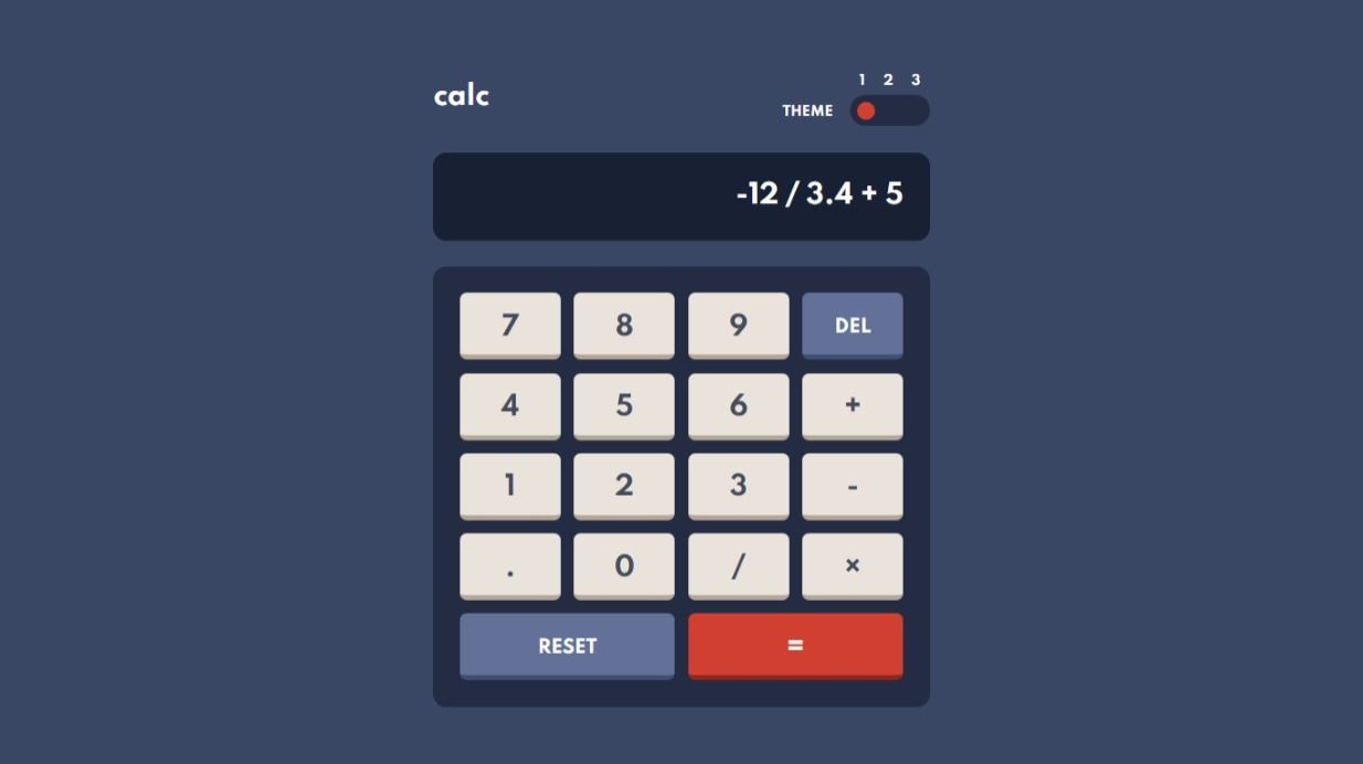
The expression on the display has five parts or tokens, as we'll call them:
- the (negative) integer
−12 - the operator
/ - the decimal
3.4 - the operator
+ - the integer
5
The machine's behaviour depends on these tokens, particularly the last one. For example, the machine can accept a DECIMAL_POINT event, because the last token is an integer. We assume that the machine stores the tokens internally, updating them as needed, while the display merely reflects what's stored. Because the machine needs to refer to individual tokens, we also assume that it stores the tokens in a list (i.e. ['-12', '/', '3.4', '+', '5']) instead of, say, a single string (i.e. '-12/3.4+5').
In a sense, the display expression is part of the 'state' of the calculator (though not one of the finite states); that's why we assume the expression is stored with the machine. In fact, the data stored with a state machine forms the extended state of the machine.
Now let's move on to modelling the machine 😃
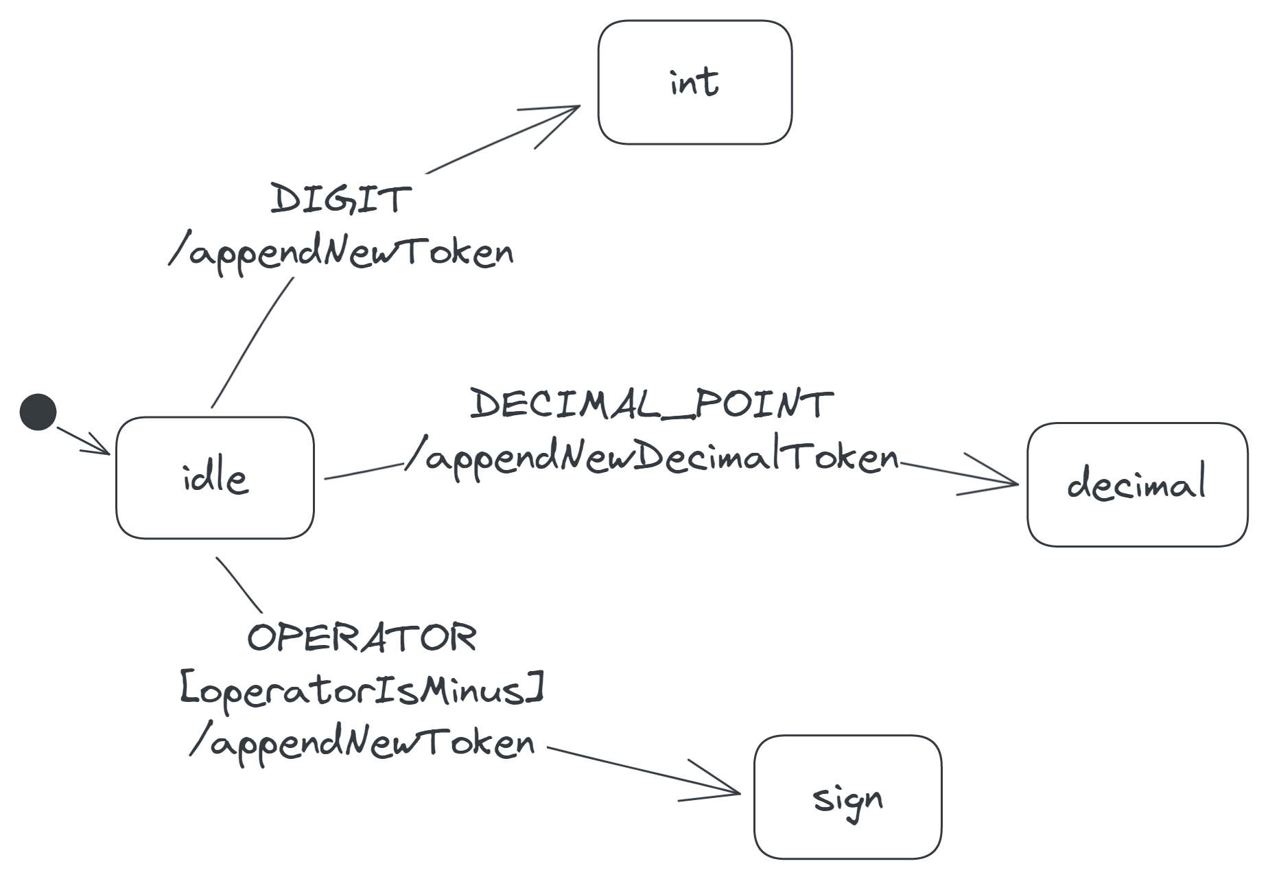
The initial state
The calculator starts with an empty display, and thus, an empty list of tokens. Let's call this state the idle state. Now when we say the calculator is in the idle state, we mean that its display is empty.
When you press a digit button here, the digit appears as a token on the display, as the following video demonstrates:
In other words, when the calculator receives a DIGIT event in the idle state, it appends the pressed digit as a new token to its token list. It also transitions to a new state, which we'll call the int (for integer) state. It moves to a new state because its behaviour when its display ends with an integer will be different from when its display is empty.
In state-diagram form:

When you press the . button in the idle state, the calculator doesn't display just the point. Instead, it displays a 0., making it clearer that the point is for a decimal:
So, when the calculator receives a DECIMAL_POINT in the idle state, it appends a new decimal token (i.e. a 0.) to its token list. It also moves to a new state, the decimal state, because its behaviour now will be different from when its display contains nothing or ends with an integer. Here's the transition diagram:

The calculator ignores any operator button you press in the idle state, because an operator mustn't be the first thing on the display. Otherwise, you may end up with an invalid expression like × 3, which has no number before the ×. An exception to this rule is the minus operator: a negative number—and thus, a minus— can begin an expression. For example, −6 / 2 is valid. The calculator responds to the − button by displaying a minus sign, as in the video below:
So, when the calculator receives an OPERATOR event and the associated operator is a minus, the calculator appends the operator to its token list. It also transitions to a new state, the sign state.
![A transition labelled 'OPERATOR[operatorIsMinus]/appendNewToken', from the idle to the sign state.](/img/5QRXx91pO8-1726.png)
Observe that the label on this transition is a bit different from the others. The text [operatorIsMinus] after the event name indicates that the machine takes this transition only if the pressed operator is a minus. This kind of condition on a transition is called a guard in state-machine terminology.
The other buttons—DEL, RESET and =—have no effect in the idle state, as there's nothing on the display to delete, reset or solve. The calculator just ignores them, so we don't add any transitions for these buttons.
Combining the transitions so far, we get the following state diagram:
The int state
Whenever the calculator is in the int state, the last token on its display is an integer. The following two screenshots show the calculator in the int state; observe that the last tokens, −32 and 7, are integers.
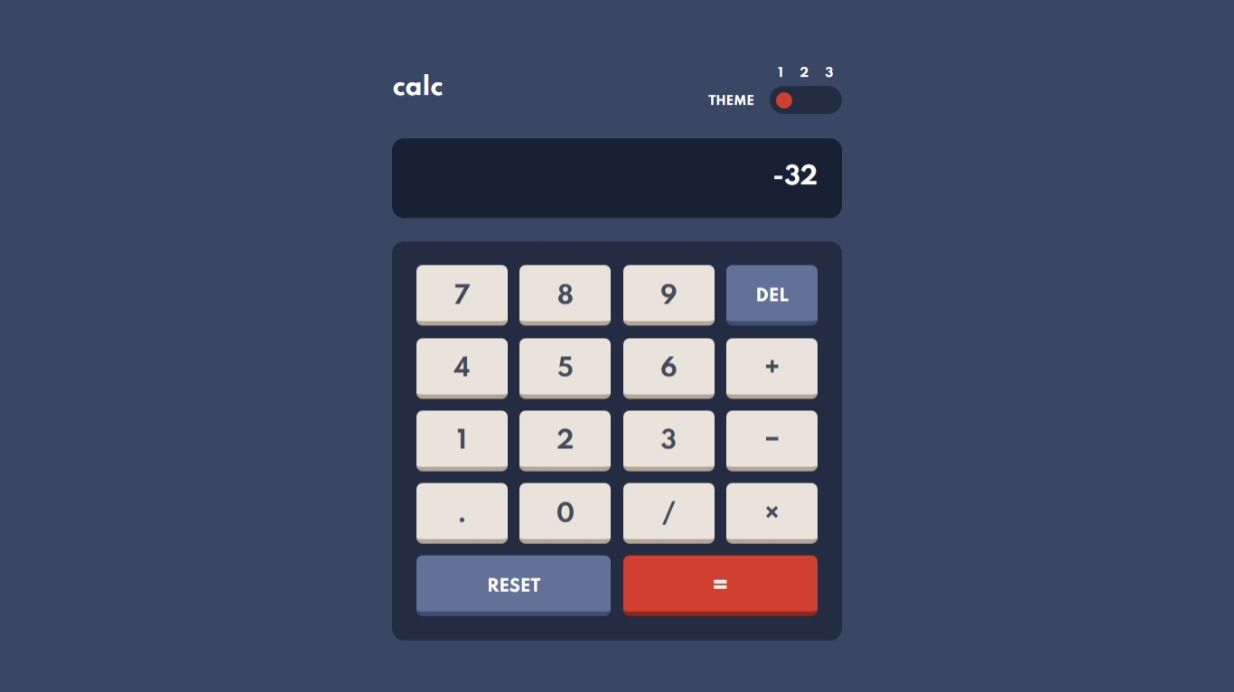
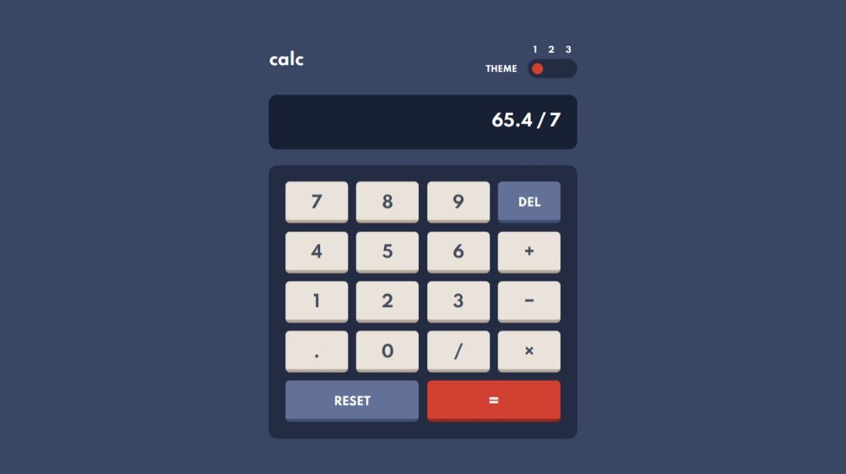
When you press a digit button in this state, the calculator appends the digit to the last token, as the video below demonstrates:
The last token in the video before pressing 3 is the integer 2; after pressing 3, the token becomes 23, which is also an integer. The last token remains an integer, so a DIGIT event in the int state causes the calculator to reenter the int state. This kind of transition, where a machine reenters its current state, is known as a self-transition.
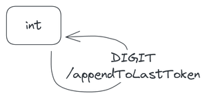
Note that the action in the above diagram is appendToLastToken not appendNewToken, because the new digit joins the last token and doesn't form a new token. Simply appending to the last token creates a slight problem, though.
Consider this situation: you press a digit, say 3, while the last token is the integer 0 or −0. The above transition would update the token to 03 or −03, respectively. However, the updated token would look odd, because, in maths, we usually don't prefix an integer with a zero. A more logical action would be, as shown in the following video, to replace the last character 0 with the new digit, making the last token 3 or −3, respectively. This was actually the behaviour of the calculator apps I tested.
We can fix this problem by adjusting the transition thus: if the last token is 0 or −0, then we replace the last character with the pressed digit; else, we append the digit to the token as before. The modified transition diagram follows.
![Two self-transitions on the int state. One is labelled 'DIGIT[lastTokenIsZeroOrMinusZero]/replaceLastChar', while the other is labelled 'DIGIT[else]/appendToLastToken'.](/img/Loplihi5HW-340.png)
An alternative diagram for this transition is given below. This diagram uses a choice pseudostate (a diamond shape) to denote the possible transitions that the DIGIT event can trigger.
![A transition labelled 'DIGIT', from the int state to a choice pseudostate, and two transitions back to the int state, labelled '[lastTokenIsZeroOrMinusZero]/replaceLastChar' and '[else]/appendToLastToken'.](/img/PVwWniD3hW-460.png)
The next event we consider is the DECIMAL_POINT. When the calculator receives this event in the int state, it appends a decimal point to its last token. If the last token is 23, for example, then it becomes 23. when you press the . button. The point in the updated token indicates that the token is no longer an integer but rather a decimal, and so the calculator has entered the decimal state.

When you press an operator button in the int state, the calculator appends the operator to the display as a new token, making the operator the last token. For example, if the display expression is −5 × 23, where 23 is the last token, and you press +, the expression becomes −5 × 23 +, and the last token, +. Because the last token is now an operator, the calculator is in a new state, which we'll call the operator state.

The transition that occurs when the calculator receives a SOLVE event is less straightforward than the ones we've discussed so far, so I'll discuss the transition later in the 'Solving the display expression' section. For the same reason, I'll delay discussing the DELETE-event transition until the 'Modelling DELETE' section.
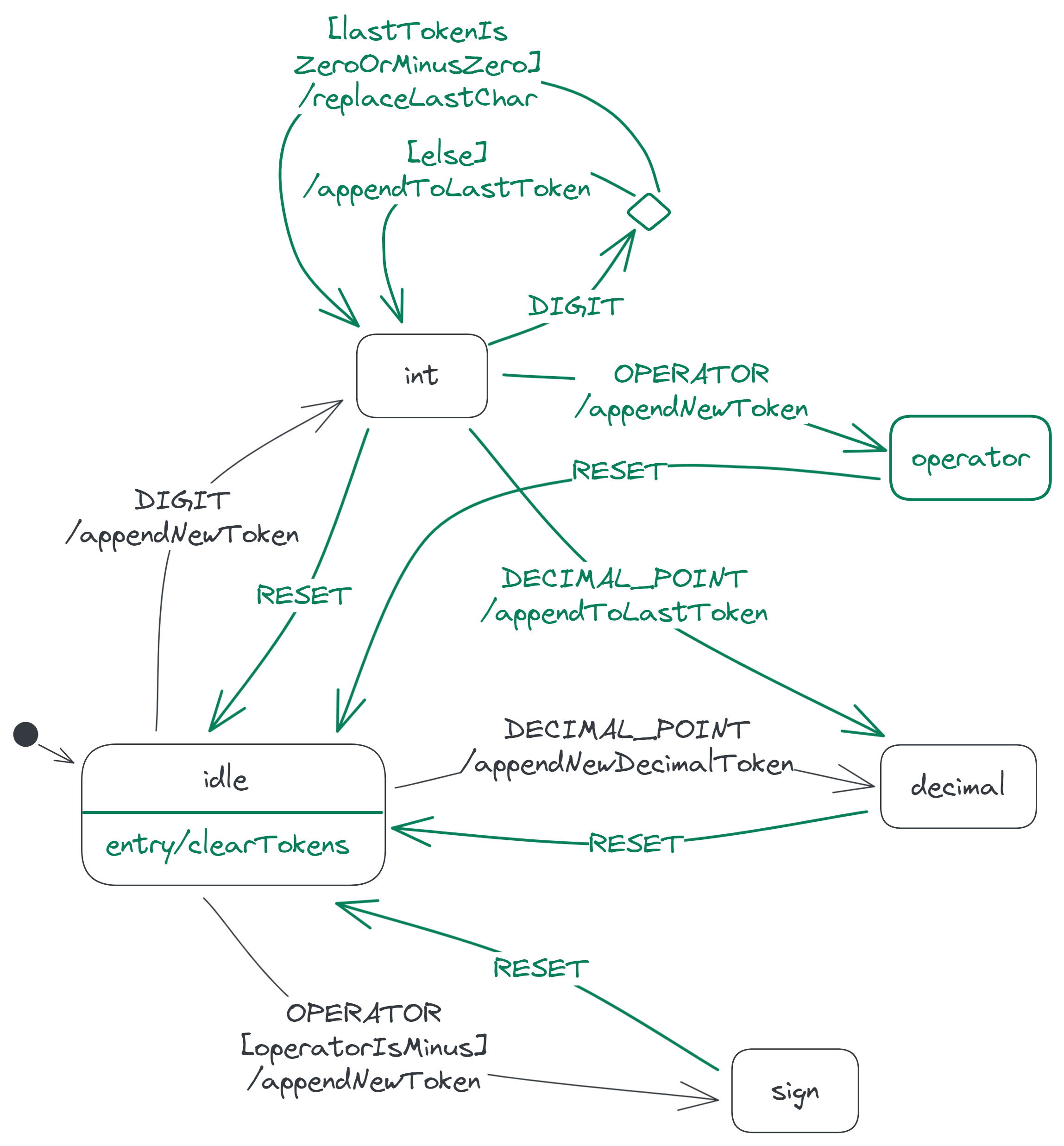
The last event to consider is the RESET event. Pressing the RESET button in the int state—or even in any other state—clears all the tokens and returns the calculator to the idle state.

The calculator actually always clears the display tokens whenever it enters the idle state (because, if you remember, the display is always empty in the idle state). To express this and thus avoid repeating the clearTokens action on other transitions to the idle state, we can instead specify the action as an entry action on the idle state:

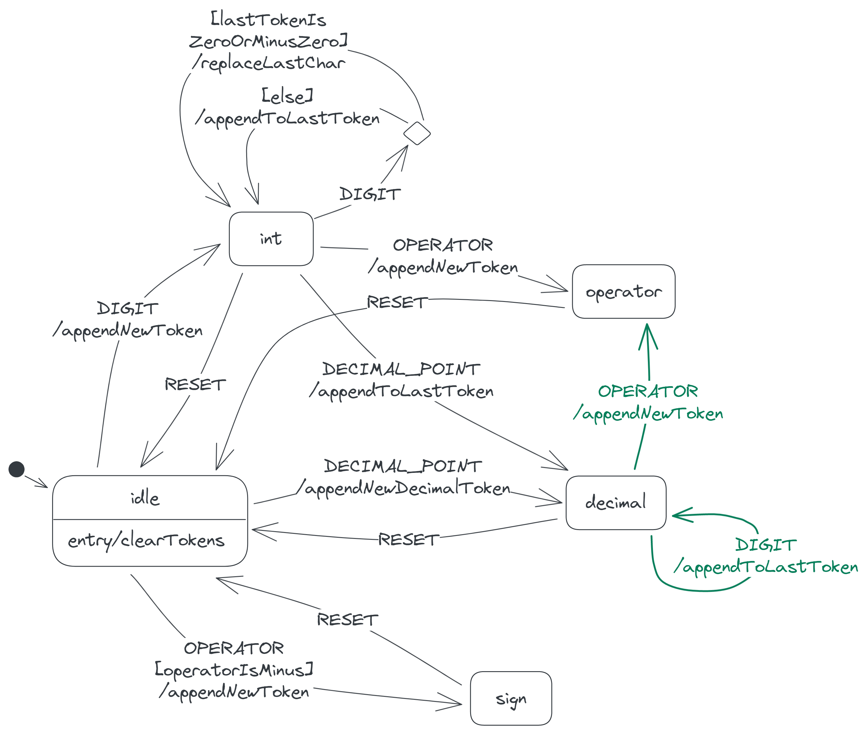
Here's the calculator state diagram so far (with the new elements highlighted in green):
The decimal state
The calculator's last token is a decimal whenever the calculator is in the decimal state.
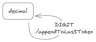
When you press a digit button in this state, the calculator appends the associated digit to its last token. For example, if you press 9 when the last token is 7.8, the token becomes 7.89. The token is still a decimal, so a DIGIT event causes the calculator to reenter the decimal state.
When you press an operator button in this state, the calculator appends the operator as a new token to its display, and moves to the operator state.

The above behaviour implicitly allows expressions like 2. / 34, where an operator follows a decimal (2.) that has no digits after the decimal point. Other calculators also allow these expressions.
Nothing happens when you press the . button in the decimal state, since the last token already contains a decimal point.
Our state diagram is now as follows:
The operator state
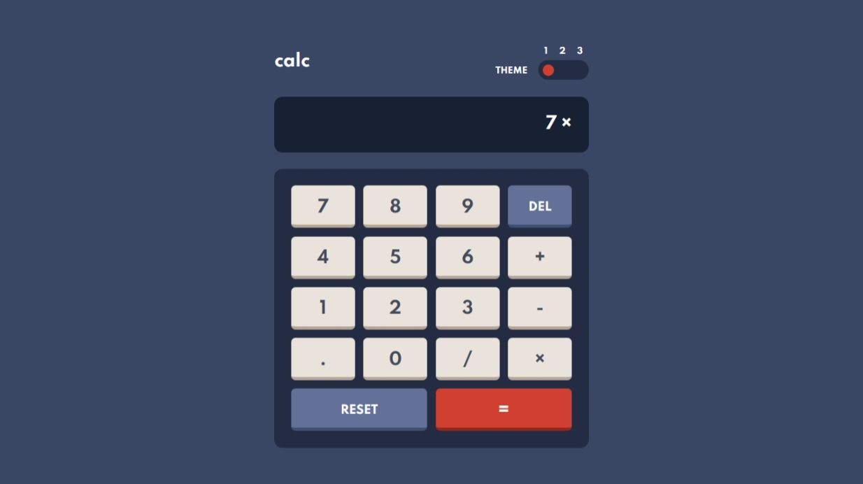
The operator state is where the last token is a binary operator—that is, an operator that's meant to be between two numbers. Therefore, in this state, the second-to-last token is a number, and the calculator expects the next token it places on its display to also be a number. Here's a screenshot of the calculator in this state:
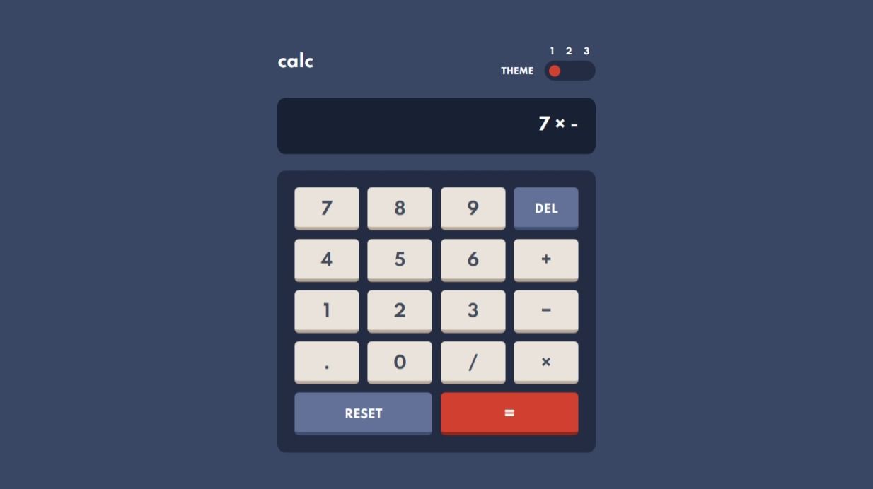
This state differs from the sign state in that the sign state is where the last token is the minus sign of a negative number, and so the second-to-last token there is never a number. The following screenshot shows the calculator in the sign state. I'll discuss this state further in the next section.
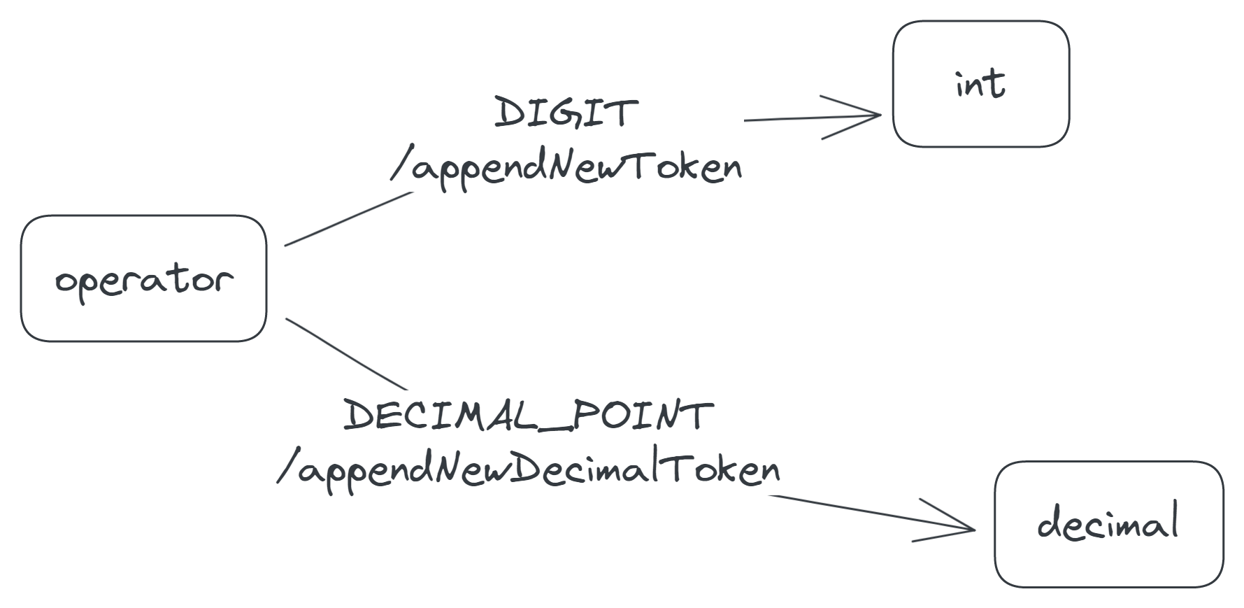
The calculator responds to the DIGIT and DECIMAL_POINT events in the operator state like it does in the idle state:
- When it receives a
DIGITevent, it appends the associated digit to its token list and moves to theintstate. - When it receives a
DECIMAL_POINT, it appends a new decimal token (0.) to its token list and moves to thedecimalstate.
In diagram form:
Now as for the OPERATOR event, the calculator responds in a particularly interesting way. If the operator accompanying the event is a +, × or /, the calculator replaces the last token with the operator, as the following video demonstrates. The assumption here is that the calculator user mistakenly chose the previous operator (the last token) and now wants to change it to a new one.
But if the operator is a minus, the calculator appends the operator to the token list to allow expressions like 7 × −2, where a negative number follows an operator. The calculator chooses this behaviour only if the last token is a × or / operator. If the last token is instead a + or −, the calculator replaces the token with the new operator like before. This therefore prevents odd expressions like 7 + −2 and 7 − −2, where a negative number follows a + or −.
To summarize, when the calculator receives an OPERATOR event in the operator state, it behaves thus:
- If the new operator is a
−and the last token is a×or/, the calculator appends the new operator to the token list. - Otherwise, the calculator replaces the last token with the new operator.
![Two transitions from the operator state. One is labelled 'OPERATOR[operatorIsMinusAndLastTokenIsMinusOrSlash]/appendNewToken', while the other is labelled '[else]/replaceLastChar'.](/img/T4eJmp0Gjz-1597.png)
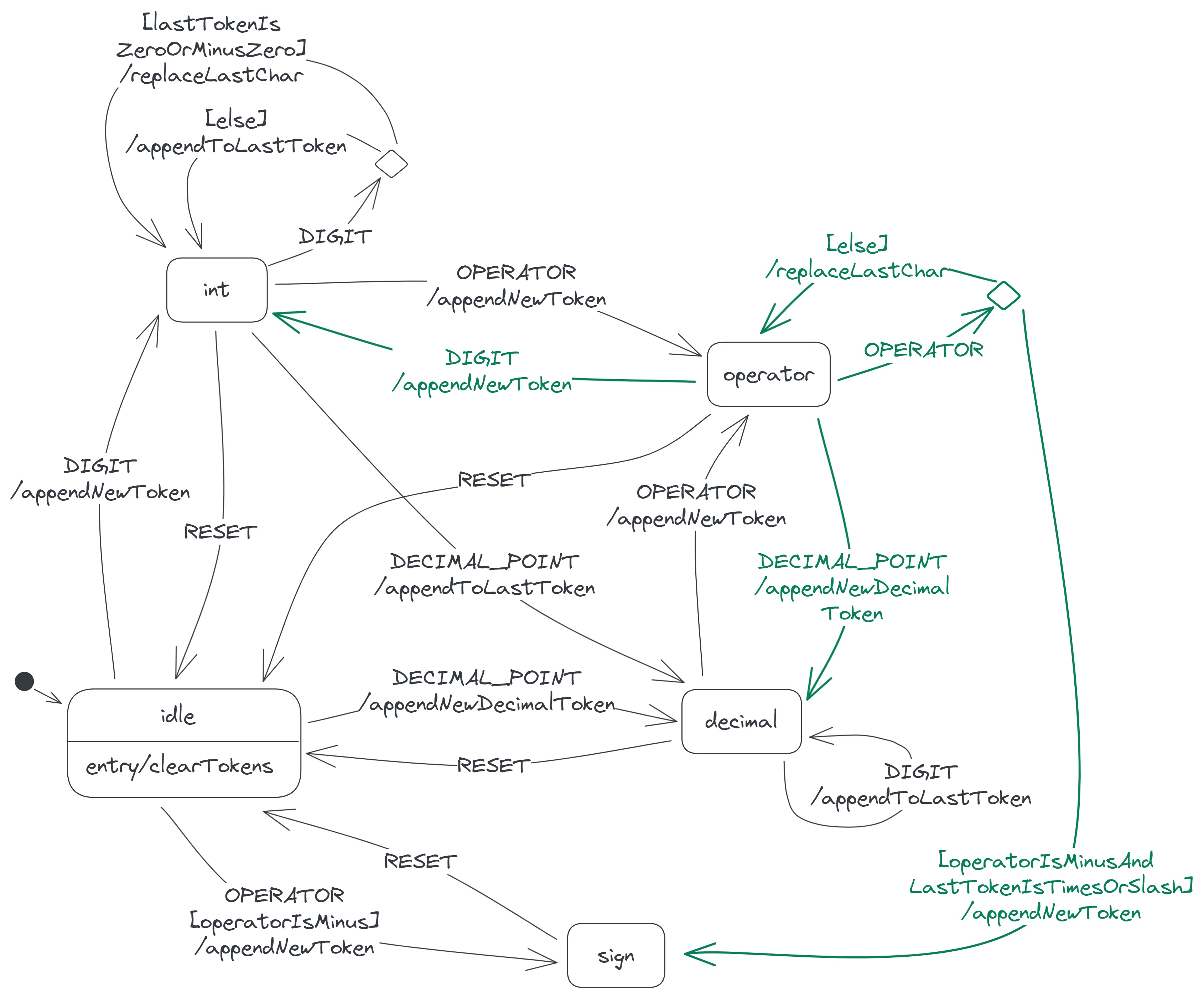
We now have the following state diagram:
The sign state
In the sign state, the last token is the minus sign of a negative number. This token may be the only token on the display, or it may follow a × or /, as in the following two screenshots:
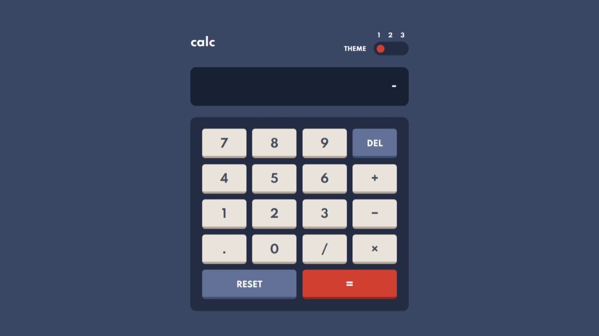

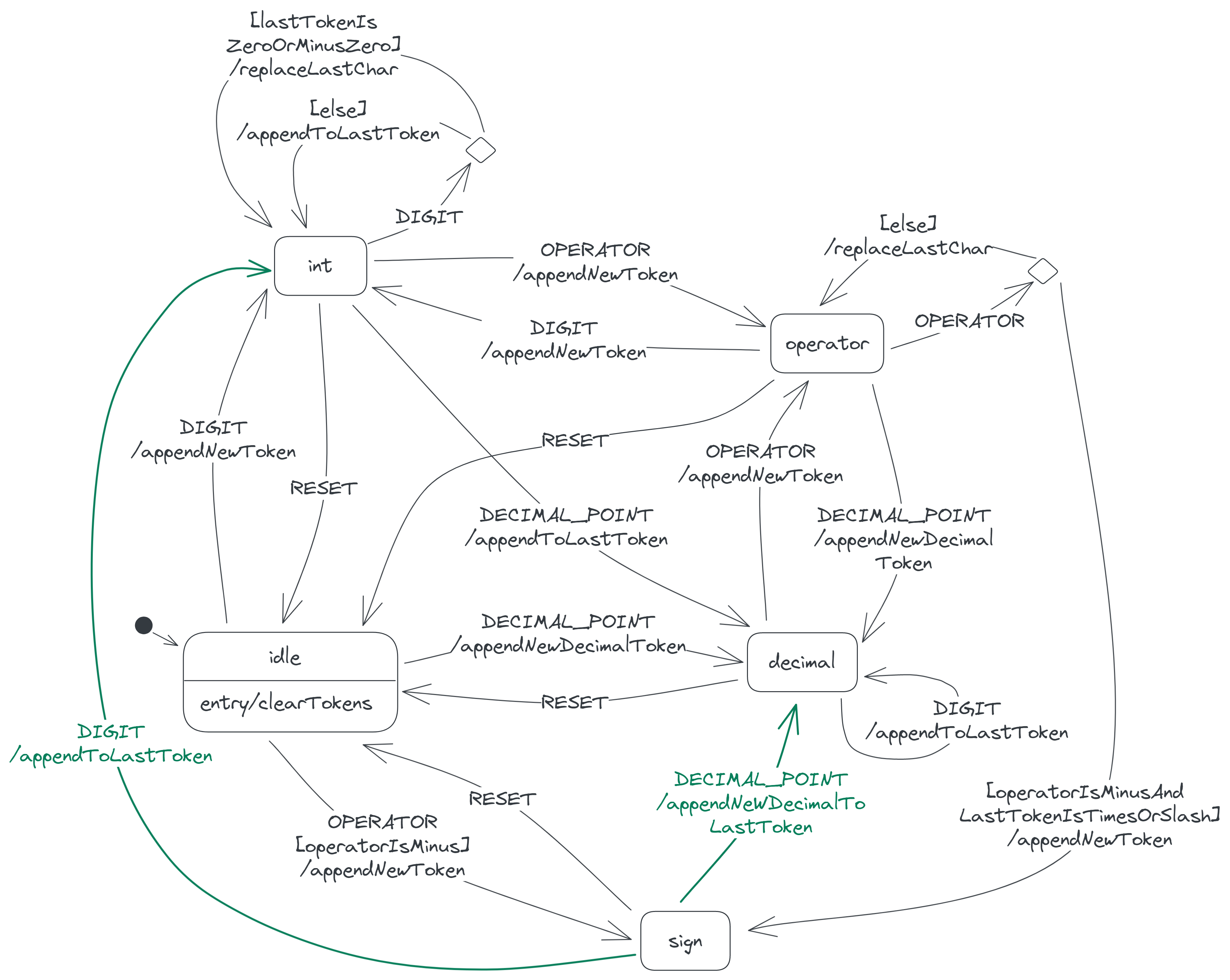
When the calculator receives a DIGIT event here, it appends the digit to the last token. So when you press 2, the last token becomes −2. The calculator also moves to the int state, since the last token becomes an integer.

When the calculator receives a DECIMAL_POINT here, it appends a new decimal (0.) to the last token and moves to the decimal state.

Adding the above two transitions to our state diagram gives:
Solving the display expression
The calculator responds to the SOLVE event only when the display expression is complete and can thus be solved. For example, the calculator responds when any of these expressions is on the display:
55 / −65 / −6.5 / −6.7
But the calculator ignores the SOLVE event when any of these incomplete expressions is on the display:
5 /5 / −
Observe that the complete expressions all end with a number token, while the incomplete ones don't. The int and decimal states are the only states where the display expression ends with a number, so these are the only states in which the calculator responds to the SOLVE event.
To respond, the calculator first evaluates the display expression. The result of this evaluation may be a number—that is, the solution—or an error, if the expression contains a division by zero (e.g. 3 / 0).
Next, the calculator replaces the expression with the result, so that the display shows just the result. The calculator also moves to either a solution or error state depending on the result. This change in state occurs because the calculator will now behave differently.
Because it needs to solve the expression to determine which of the two states to enter, the calculator can't transition directly to either state when it receives the SOLVE event. It instead transitions to an intermediate solving state, where it solves the expression via a solve action:
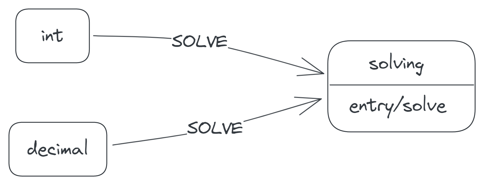
The solve action doesn't just solve the display expression; it also sends the result back to the calculator through an event, since the calculator needs the result to make the next transition. (Yes, actions can generate events.) If the result is a solution, the action sends a DONE event along with the solution as the event data. Otherwise, the action sends an ERROR event along with the error message, 'Cannot divide by zero'.
On receiving the DONE or ERROR event in the solving state, the calculator transitions to the solution or error state, respectively. Finally, on entering either state, the calculator replaces all the display tokens with the new result token:
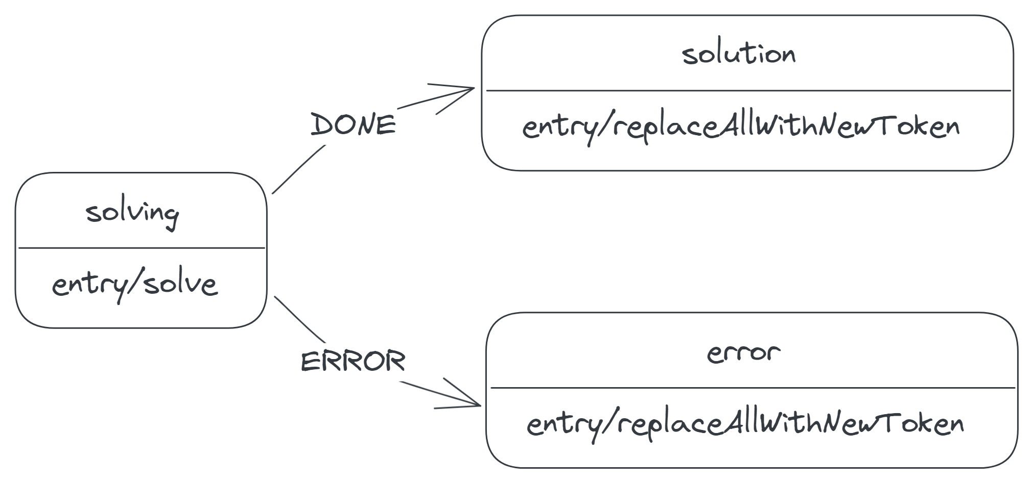
In practice, the solve action happens very fast, so the calculator leaves the solving state immediately after entering.
Let's now see how the calculator behaves in the result states, solution and error.
The result states
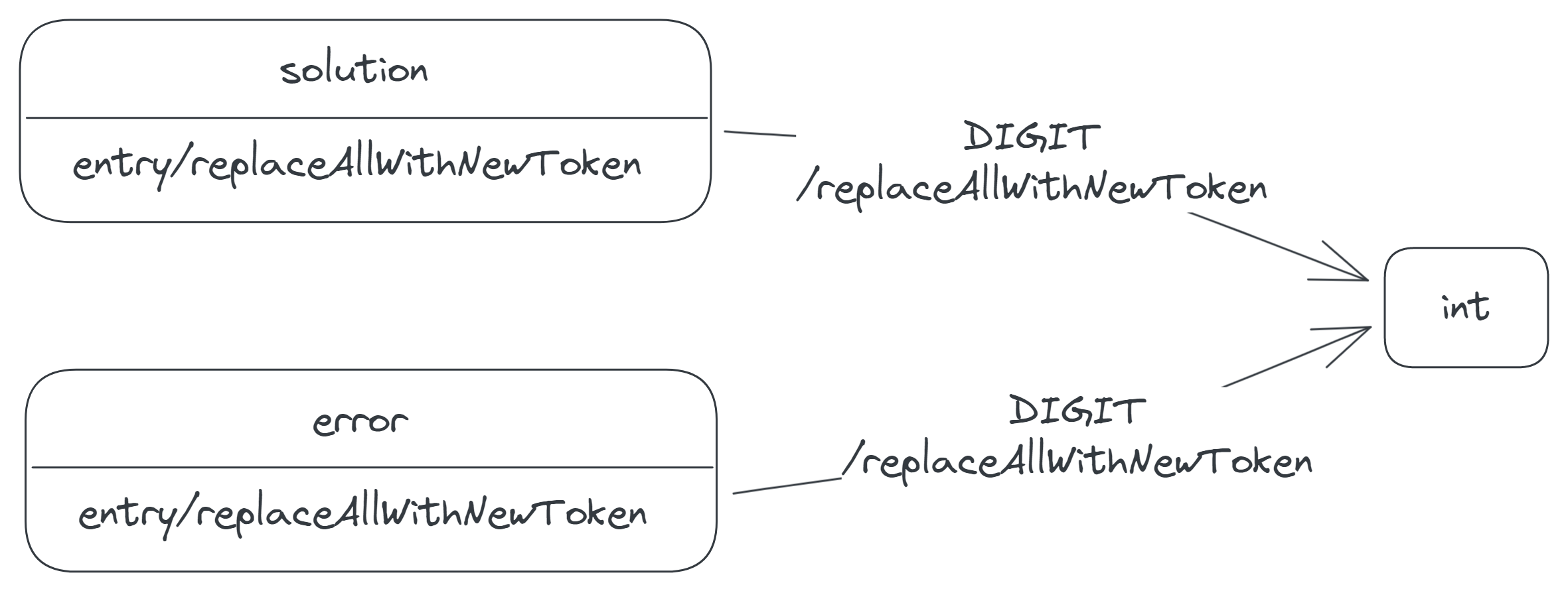
If the calculator receives a DIGIT event in either result state, the calculator replaces all its display tokens with the incoming digit and moves to the int state. This behaviour assumes that by pressing a digit button, a user wants to begin a new calculation.
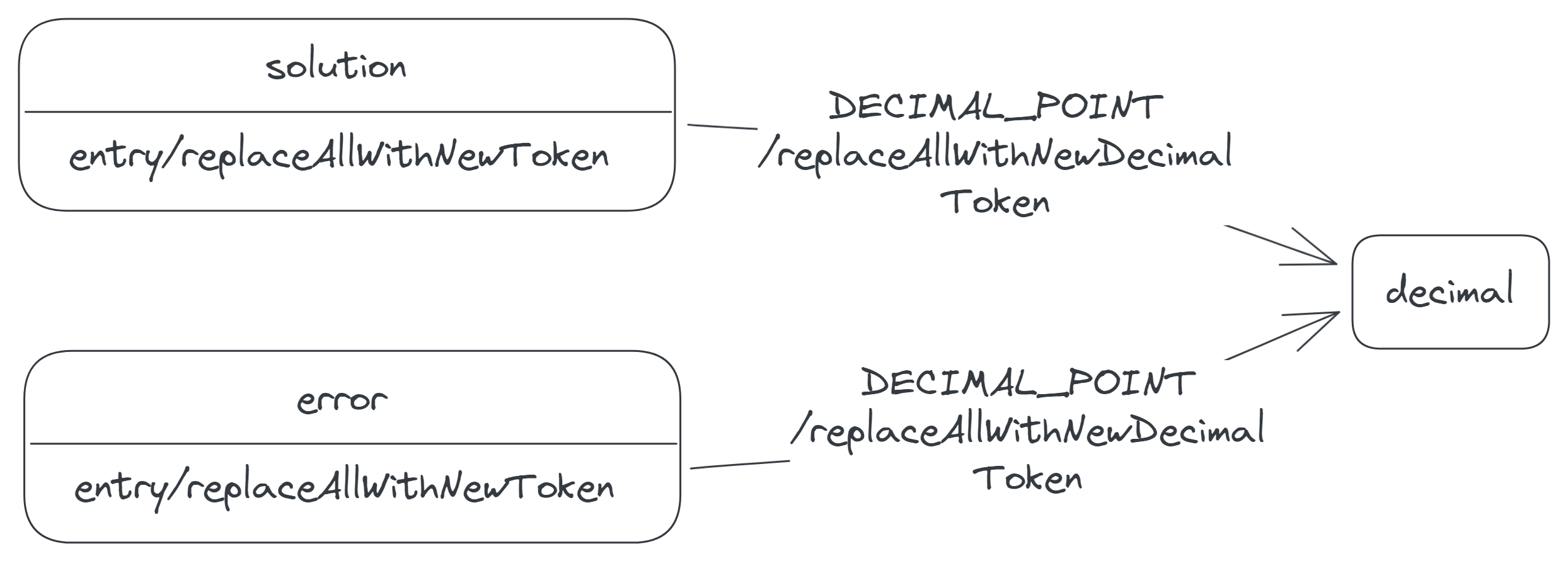
Similarly, if the calculator receives a DECIMAL_POINT event in either result state, the calculator replaces all its display tokens with a new decimal token (0.) and moves to the decimal state.
The difference between the solution and error states is in how the calculator responds to the OPERATOR event. When the calculator receives this event in the solution state, it appends the accompanying operator to its token list, as the following video demonstrates. This behaviour allows the user to conveniently reuse the solution of a previous calculation in a new calculation.

The calculator however ignores this event in the error state, since it doesn't make sense for an operator to follow an error message. It also doesn't make sense for an operator to replace the message, since, as we mentioned before, an operator mustn't be the first thing on the display. Unless—as you may guess—the operator is a minus. A minus can be the first thing on the display, so the calculator responds to the minus-OPERATOR event by replacing the message with the operator and moving to the sign state.
![A transition labelled 'OPERATOR[operatorIsMinus]/replaceAllWithNewToken', from the error to the sign state.](/img/SlqLyniOdW-2418.png)
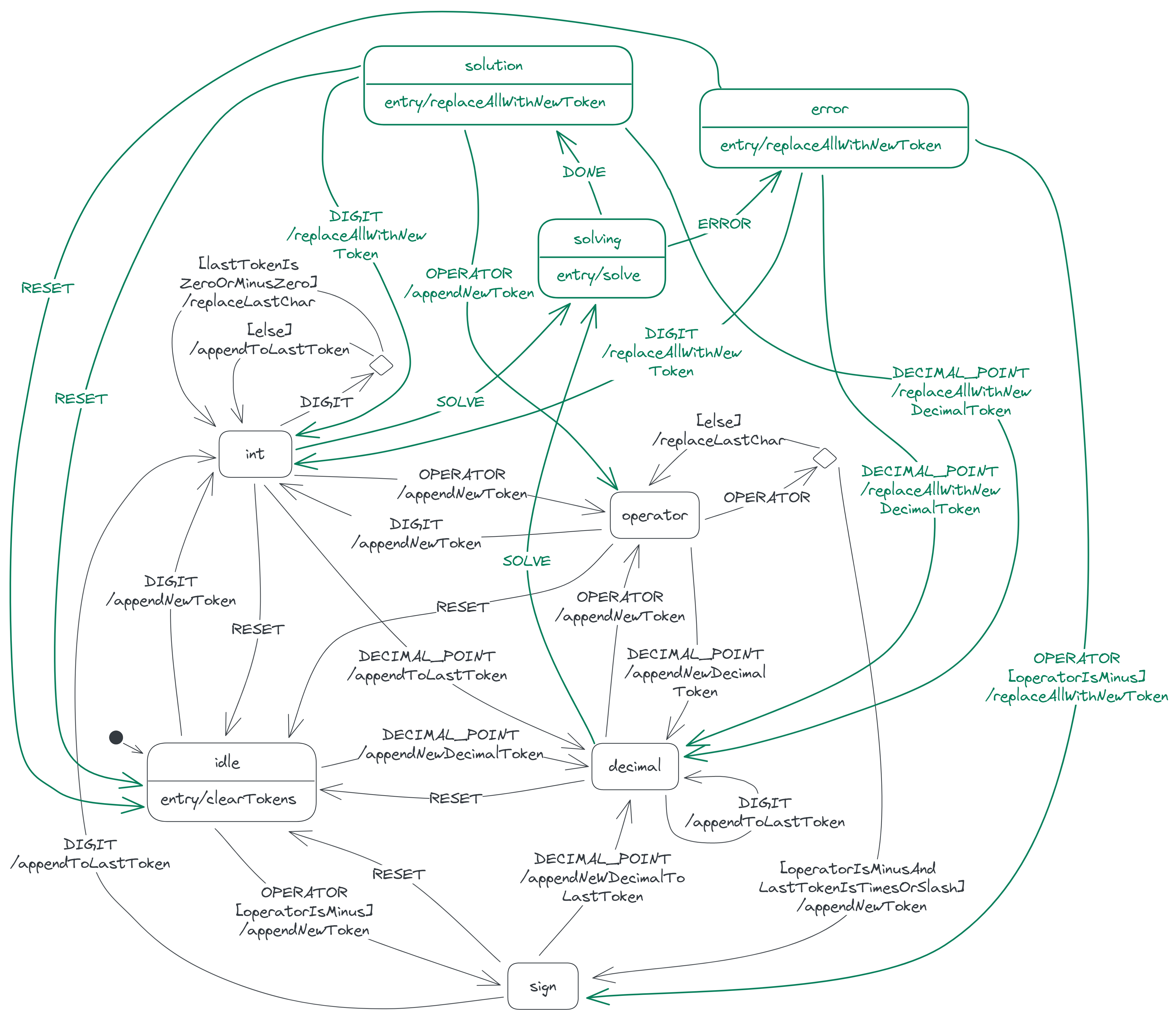
Our calculator state diagram is now as follows:
Modelling DELETE
The DELETE event generally causes the calculator to remove the last character on the display. Let's explore the transitions the calculator makes when it receives this event in different states.
DELETE in the int state
Remember that in the int state, the last token is an integer. This token may comprise a single digit or many digits, may or may not have a negative sign and may be the only token on the display or the next token after an operator. These factors influence which state the calculator ends up in when it receives a DELETE event in the int state.
If the last token is an unsigned digit and also the only token on the display, as in the expression 1, then the DELETE event moves the calculator to the idle state.
If the last token is a signed digit, as in the expressions −2 and 3 × −4, then the DELETE event reduces the token to a minus sign (i.e. the expressions become − and 3 × −, respectively) and moves the calculator to the sign state.
If the last token is an unsigned digit that follows an operator, as in 5.6 + 7, then the event removes the token from the display, making the operator the last token and moving the calculator to the operator state.
If none of the above conditions is true of the last token—that is, if the token comprises more than one digit, as in the expressions 89 and 0. / −123—then the event simply removes the last digit, keeping the calculator in the int state.
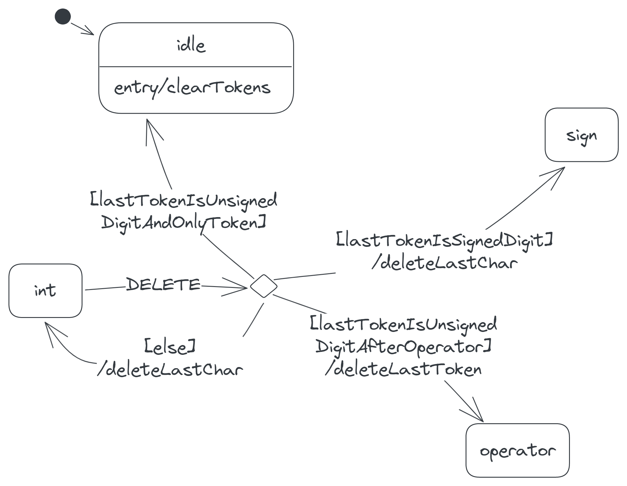
Note that the diagram includes two different actions for deleting the last character on the token list: deleteLastChar and deleteLastToken. We differentiate these actions, because deleting the last character on the token list may or may not require removing the last token as well.
The deleteLastChar action deletes the last character of the last token without removing the token. For example, the action reduces the token list ['0.', '/', '123'] to ['0.', '/', '12']. Similarly, the action reduces the list ['5.6', '+', '7'] to ['5.6', '+', ''], where the last token is an empty string. A token can't be an empty string, so the deleteLastChar action is inappropriate when the last token is a single character.
What is appropriate in this situation, however, is the deleteLastToken action. This action deletes the last token and thus reduces the list ['5.6', '+', '7'] to ['5.6', '+']. We use this action only when the last token is a single character, but we use the other action otherwise.
DELETE in the decimal state
Where the calculator transitions to from the decimal state depends on whether the last token here has digits after its decimal point. If the last token has one or more digits after its decimal point, as in −4.56, then on receiving the DELETE event, the calculator remains in the decimal state (i.e. the token becomes −4.5, which is still a decimal).
If, however, the last token ends with a decimal point, as in 7 + 8., then the DELETE event reduces the last token to an integer and thus moves the calculator to the int state.
![Two DELETE transitions from the decimal state: one labelled '[lastTokenEndsWithDecimalPoint]/deleteLastChar' entering the int state, and another labelled '[else]/deleteLastChar' reentering the decimal state.](/img/mh2NqS8D6L-1851.png)
DELETE in the operator state
The last token in the operator state is an operator that follows a number—integer or decimal. So the DELETE event in this state has one of two outcomes:
If the number preceding the last token is an integer, as in the expression −9 /, the calculator deletes the last token and transitions to the int state.
But if the preceding number is a decimal, as in 0.12 −, then the calculator deletes the last token and transitions to the decimal state.
![Two DELETE transitions from the operator state: one labelled '[secondToLastTokenIsInteger]/deleteLastToken' entering the int state, and another labelled '[else]/deleteLastToken' entering the decimal state.](/img/4kmK9iitAf-1860.png)
DELETE in the sign state
In the sign state, the last token (a minus) may be the only token on the display, as in the expression −, or it may follow an operator, as in 3 × −.
In the former case, the DELETE event returns the calculator to the idle state. But in the latter, the event takes the calculator to the operator state.
![Two DELETE transitions from the sign state: one labelled '[lastTokenIsOnlyToken]' entering the idle state, and another labelled '[else]/deleteLastToken' entering the operator state.](/img/2_tdXvVD-0-1808.png)
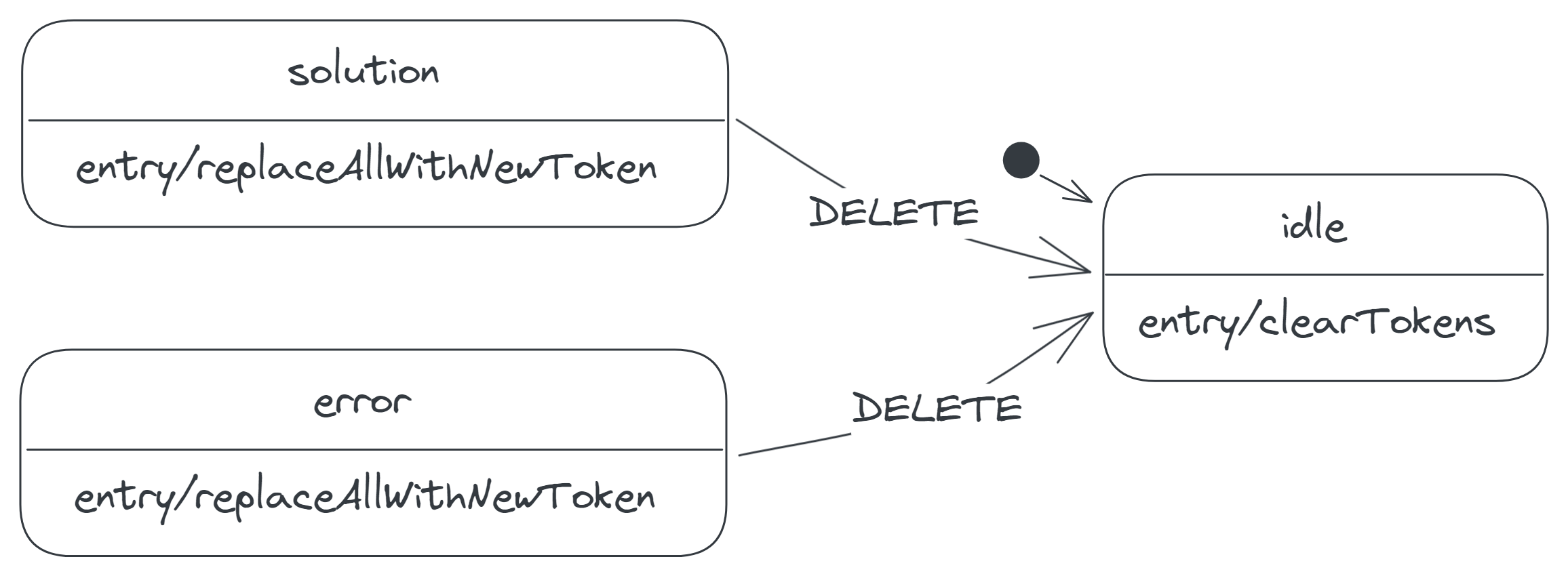
DELETE in the result states
In the solution and error states, the DELETE event has the same effect as the RESET event: it returns the calculator to the idle state.
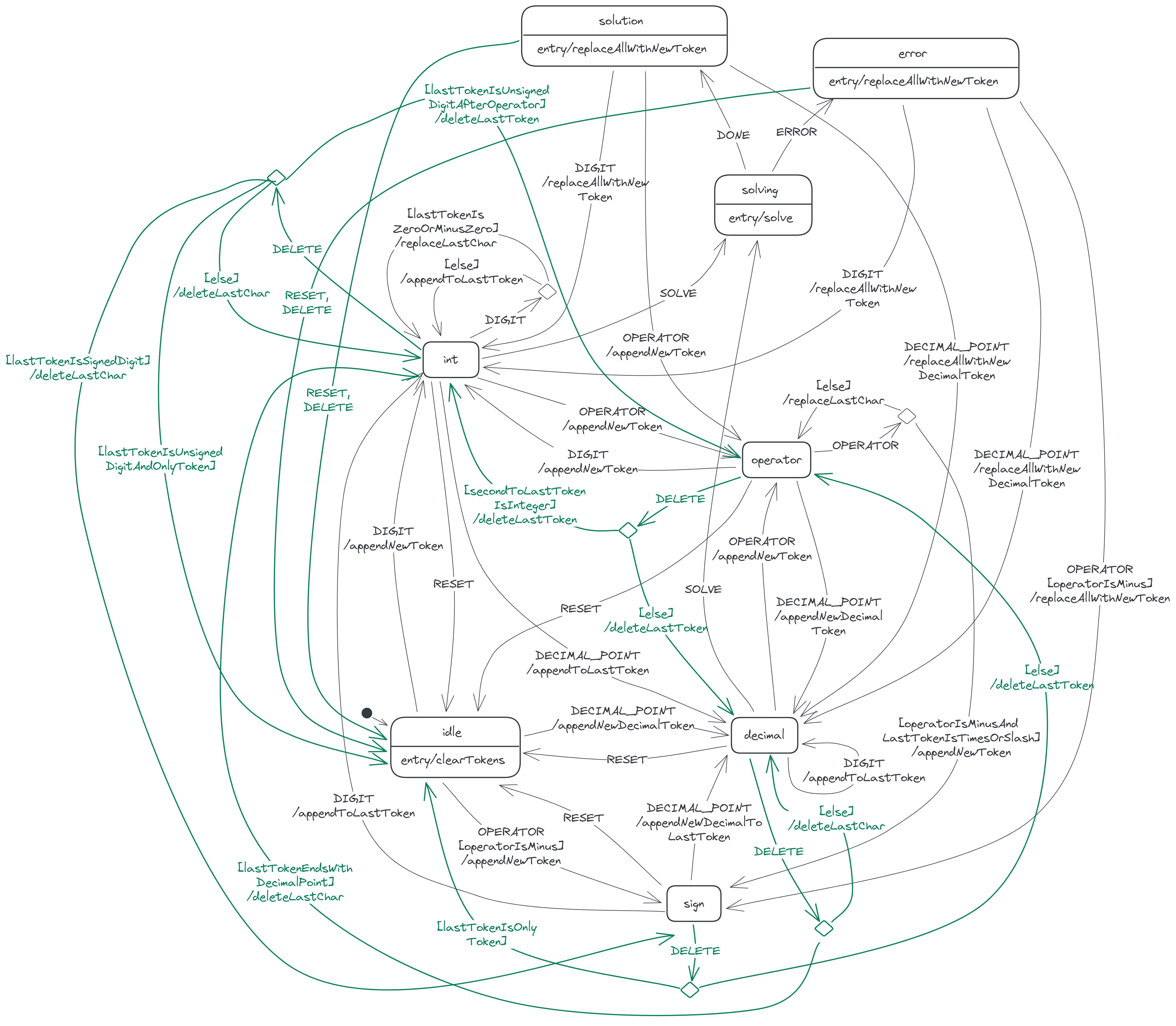
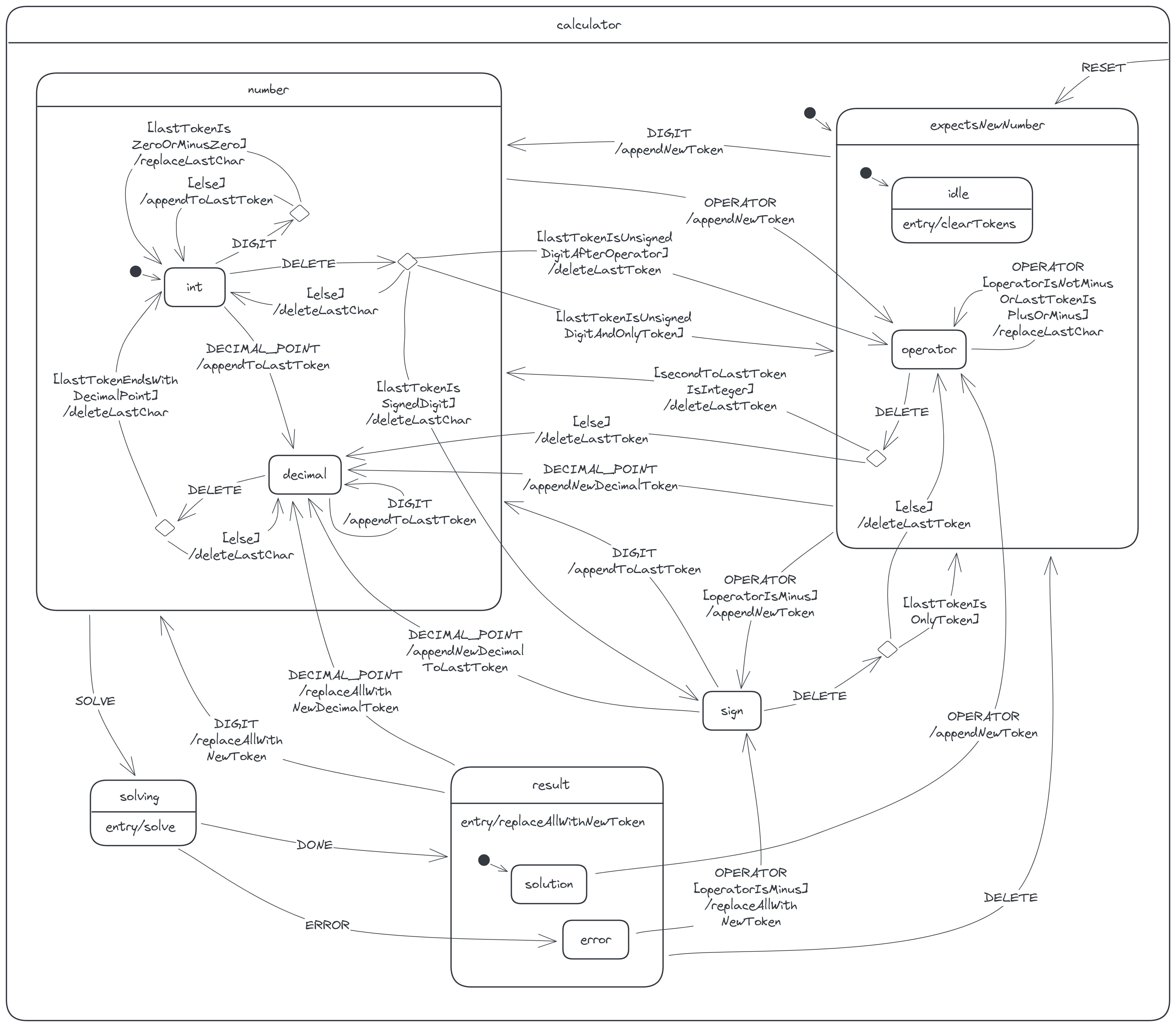
We're now done modelling the calculator machine; we've specified all the states and all the allowed transitions between the states. Here's the complete state diagram:
A tidier diagram
One problem with our state diagram is that it is somewhat messy and difficult to follow, because of the many transition arrows present in it. Imagine how messier the diagram would be if the calculator were more complex! To avoid this problem, I actually didn't model the calculator using the 'flat' state diagram I've so far described. I've presented the calculator in this manner, just to lay the foundation for the actual diagram I used, a statechart, which I'll now describe.
As we were modelling, you probably noticed that some states share the same transitions:
- The
intanddecimalstates share the sameOPERATORandSOLVEtransitions. - The
idleandoperatorstates share the sameDIGIT,DECIMAL_POINTand minus-OPERATORtransitions. - The
solutionanderrorstates share the sameDIGIT,DECIMAL_POINTandDELETEtransitions. - All states share the same
RESETtransition.
A statechart allows us to cluster these related states into superstates and then move the common transitions from the individual states to just the superstates. This way, a statechart helps us reduce the number of arrows significantly. Let's upgrade our state diagram to a statechart!
The int and decimal states are the two states where the last display token is a number (an integer or a decimal), so we cluster these states into a number state, as follows:
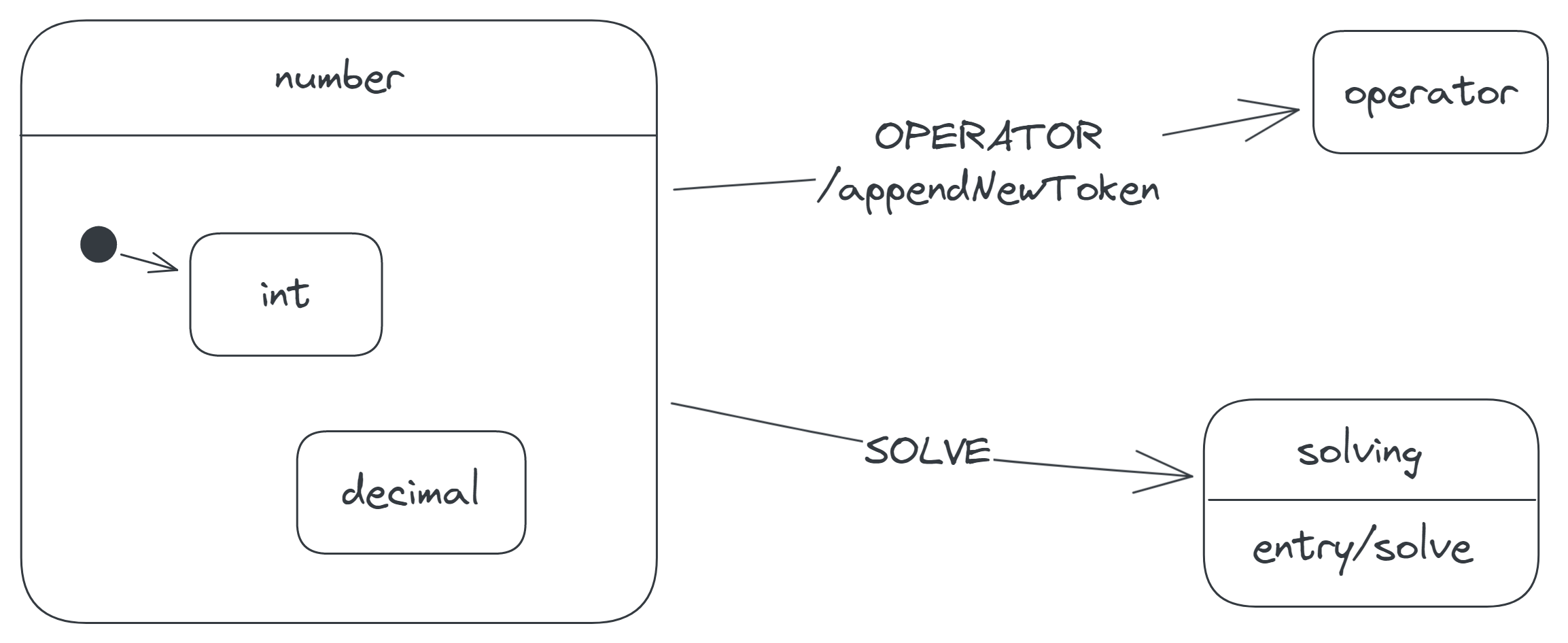
Clustering these states changes how we interpret the diagram. First, whenever the calculator is in the int or decimal state, the calculator is also in the number state; conversely, whenever the calculator is in the number state, the calculator is also either in the int or decimal state.
Second, observe that the int state now has an initial-state arrow pointing to it. This arrow indicates that whenever the calculator enters the number state, it also enters the int state by default.
Third, suppose the calculator receives a SOLVE event while in the int state. To determine which transition the calculator makes, we start by checking for a SOLVE transition attached to the int state. Since there's none, we check the parent state of the int state—that is, the number state—for any such transition. The number state has a SOLVE transition, so we choose this transition. If the number state also had none, we would check its parent, if it had a parent, and so on. When we reach a state that has no parent (e.g. the number state), and we don't find any SOLVE transition, we conclude that the calculator ignores the SOLVE event in the int state.
The next states to consider are the idle and operator states. In these states, the calculator generally expects the next token it places on its display to be a new number. We cluster these states into an expectsNewNumber state:
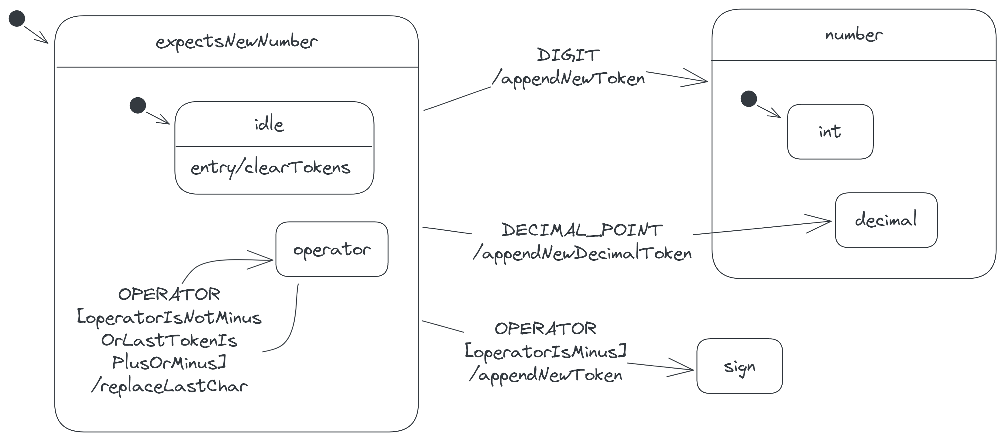
Observe that the expectsNewNumber state has an initial-state arrow entering it. This is because the state contains the initial state of the calculator, the idle state. Thus, the diagram tells us that the calculator starts in the expectsNewNumber state, which in turn defaults to the idle state.
Also observe that the operator state still has an OPERATOR self-transition, but the guard on the transition is now operator. Previously, when the operator state had two OPERATOR transitions, the guard on the one leading to the sign state was operator, while the guard on the self-transition was simply else. Now that the former transition is no longer attached to the operator state, we write the guard on the latter in full by inverting the guard on the former. So the new guard operator is just the opposite of operator.
The next states to consider are the solution and error states; we cluster them into a result state. The two states also share the same entry action, so we move the action to just the result state:
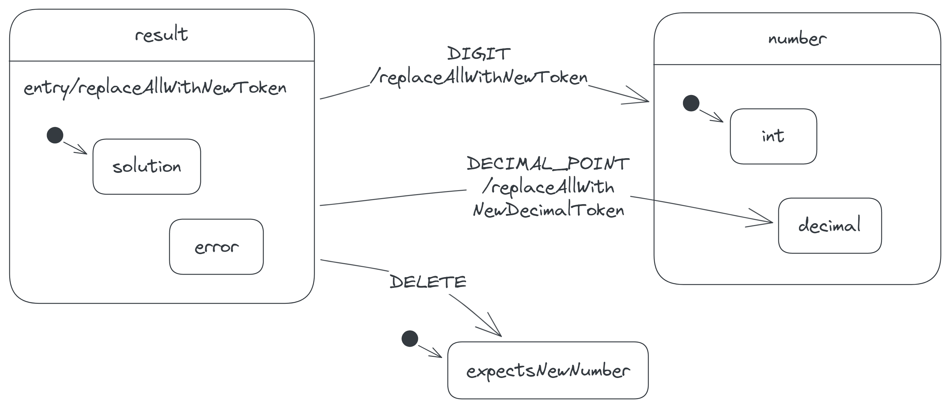
Notice that the child states of the expectsNewNumber state are absent in the diagram, since they're irrelevant there. Statecharts allow us to 'zoom out' of states in this manner.
Finally, we cluster all states into a single superstate to avoid repeating the RESET transitions. We call this new superstate the calculator state, because it encloses all other states and thus represents the calculator machine itself. Though this state contains the initial state of the calculator, it doesn't need an initial-state arrow, since it already represents the calculator:
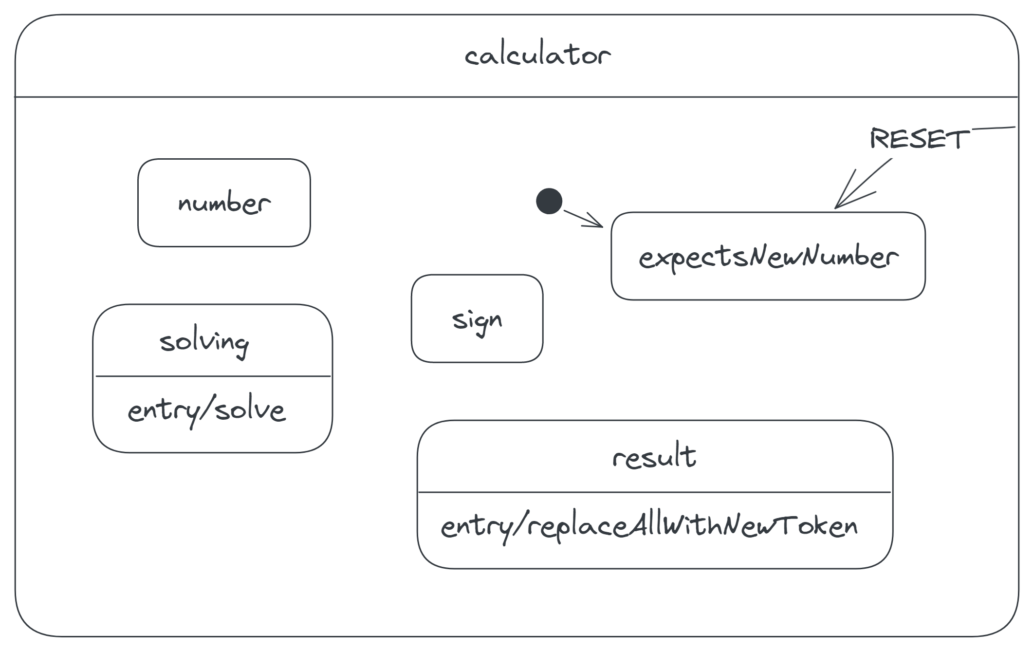
Our complete calculator diagram now looks tidier:
Translating to code
While our calculator model is complete and robust, it's still just a model. We need to convert it to executable code somehow, if we're going to use it in the calculator app. Thankfully, we don't have do this conversion entirely by hand; we can use tools such as Stately Studio to auto-generate the central code for our model. In this section, I'll briefly present the code I generated from Stately Studio and explain how I integrated the code with the rest of the calculator app.
Stately Studio is an online tool for modelling state machines and statecharts. It allows you to create models, simulate the models and export them as declarative JavaScript, TypeScript or JSON code. The exported code is then meant to be used with Stately Studio's companion JavaScript library, XState.
The JavaScript code for the calculator statechart is as follows. (I've edited and annotated it for clarity and brevity.) The code calls a createMachine function, which comes from XState, with an object describing the calculator machine. The function in turn creates and returns the machine.
import { createMachine } from "xstate";

const calcMachine = createMachine({
	// The ID of (the outermost state of) the machine.
	id: "calculator",

	// The initial state of the machine.
	initial: "expectsNewNumber",

	// The 'context' object specifies the initial extended state.
	// Here the object contains just an empty array of tokens.
	context: {
		tokens: [],
	},

	// The keys of the 'states' object are the names of
	// the child states of the calculator state.
	states: {
		number: {
			// ...
		},
		expectsNewNumber: {
			// ...
		},
		sign: {
			// ...
		},
		solving: {
			// ...
		},
		result: {
			// ...
		},
	},

	// The 'on' object here specifies the transitions attached
	// to the calculator state.
	on: {
		// The only transition is the RESET-event transition.
		RESET: {
			// This transition moves the machine to the target
			// state, expectsNewNumber. The dot prefix indicates
			// that the state is a child of the calculator state.
			target: ".expectsNewNumber",
		},
	},
});
Each state in the states object is then defined recursively using an object similar to the one above. For example, the result state is defined thus:
{
  result: {
    // The entry action of the result state.
    entry: "replaceAllWithNewToken",

    // The default child state of the result state.
    initial: "solution",

    // The child states of the result state.
    states: {
      solution: {
        // ...
      },
      error: {
        // ...
      },
    },

    // Transitions attached to the result state.
    on: {
      DIGIT: {
        target: "number",
        actions: "replaceAllWithNewToken",
      },

      DECIMAL_POINT: {
        // This transition leads to the decimal state, which
        // is a child of the number state, which is in turn a
        // child of the outermost calculator state. The full path
        // is used here, because the decimal state is not a sibling
        // or child of the result state.
        target: "#calculator.number.decimal",
        actions: "replaceAllWithNewDecimalToken",
      },
    },
  },
}
The inner states are similarly defined too. For example, the error state is as follows:
{
  error: {
    on: {
      OPERATOR: {
        target: "#calculator.sign",
        // 'cond' specifies the guard.
        cond: "operatorIsMinus",
        actions: "replaceAllWithNewToken",
      },
    },
  },
}
If you're following carefully, you'll notice that the exported machine definition is incomplete, as it doesn't define the actions and the guards, despite naming them. That is, the code mentions appendNewToken as an action but doesn't say how exactly to append a new token. Similarly, the code mentions operatorIsMinus as a guard but doesn't specify how to determine if an incoming operator is a minus.
To complete the definition, we manually implement the actions and guards in a second object argument:
import { createMachine, assign } from "xstate";

const calcMachine = createMachine(
	{
		// ...
	},
	// The second argument defines the actions and guards.
	{
		actions: {
			// We define 'appendNewToken' using the 'assign' function
			// from XState, because the action modifies the machine's
			// context (i.e. the action modifies the token list).
			appendNewToken: assign({
				// The 'tokens' property here specifies how to update
				// the corresponding property in the context. Its value
				// is a function that takes the current context and the
				// triggering event and returns a new, updated token list.
				tokens: (context, event) => {
					const newToken = event.data;
					return [...context.tokens, newToken];
				},
			}),

			// Other actions...
		},

		guards: {
			// Each guard is a function that takes the current context
			// and the triggering event and returns a boolean.
			operatorIsMinus: (context, event) => {
				return event.data === "-";
			},

			// Other guards...
		},
	}
);
After completing the definition, we connect the machine to the calculator UI, so that the buttons can send events to the machine, and the machine can update the display in response. We achieve this in three steps:
First, we create a running instance of the machine, called a service, by passing the machine to an interpret function from XState. This service is what the UI will directly interact with:
import { createMachine, assign, interpret } from "xstate";

const calcMachine = createMachine(/* ... */);

const calcService = interpret(calcMachine).start();
Next, we attach to each button a listener that sends an appropriate calculator event to the service whenever the button is clicked. Each calculator event is an object with a type property (e.g. DIGIT) and an optional data property:
// The buttons have a 'Button' CSS class to identify them.
const buttons = document.querySelectorAll(".Button");

buttons.forEach((button) => {
	button.addEventListener("click", () => {
		const text = button.textContent.toUpperCase();

		if (isDigit(text)) {
			calcService.send({ type: "DIGIT", data: text });
		} else if (isOperator(text)) {
			calcService.send({ type: "OPERATOR", data: text });
		} else if (text === ".") {
			calcService.send({ type: "DECIMAL_POINT" });
		} else if (text === "=") {
			calcService.send({ type: "SOLVE" });
		} else if (text === "DEL") {
			calcService.send({ type: "DELETE" });
		} else if (text === "RESET") {
			calcService.send({ type: "RESET" });
		}
	});
});

function isDigit(str) {
	return ["0", "1", "2" /* ... */, , "9"].includes(str);
}

function isOperator(str) {
	return ["+", "−", "×", "/"].includes(str);
}
Finally, we update the display whenever the machine makes a transition:
const display = document.querySelector(".Display");

calcService.onTransition((state) => {
	// Join the token list into a single expression string.
	const expression = state.context.tokens.join(" ");
	display.textContent = expression;
});
You can find the complete code on GitHub. I actually wrote the code in TypeScript (which is basically a safer JavaScript) and split the code into two files, because of its length: machine.ts for the machine definition and index.ts for the rest.
One thing I really like about the code is how easy it is to extend. My calculator initially didn't have some important behaviours I described in this article, because I didn't think of them until I began writing the article. Updating the code to include each of these behaviours involved three steps in general:
- Find the state in which the behaviour is missing.
- Identify the event that should trigger the behaviour.
- Add to the state a new transition (including relevant actions and guards) triggered by the event.
The first two steps were particularly straightforward, because the states and events were already clearly defined. The third step often required more thought, but I could still perform the step conveniently in Stately Studio.
Another thing worth mentioning is that, despite the state machine, the code isn't free of bugs. If you try calculating an expression as basic as 0.1 + 0.2 on the calculator, you'll get a wrong answer, 0.30000000000000004, instead of 0.3. The source of this bug is the solve action implementation (shown below). The action passes the display expression directly to JavaScript to evaluate (via JavaScript's eval function). However, like many other programming languages that represent numbers with the binary floating-point format, JavaScript can't accurately solve every expression involving decimals.
{
  // The 'solve' action is defined using the 'send'
  // function from XState, because the action sends
  // an event back to the machine.
  solve: send((context, event) => {
    const expression = context.tokens.join("");

    // Pass the expression to JavaScript to evaluate.
    const result = eval(expression);

    // A finite result indicates that no error
    // (such as a division by zero) was encountered
    // while evaluating the expression.
    if (Number.isFinite(result)) {
      return { type: "DONE", data: `${result}` };
    } else {
      return { type: "ERROR", data: "Cannot divide by zero" };
    }
  }),
}
What's interesting about this bug is that it comes from the implementation of an action and not from the model itself. So fixing the bug is just a matter of editing the implementation. While state machines don't prevent every UI bug, they prevent bugs that arise from a UI's overall reaction to different series of inputs and, as a result, relegate most bugs to places like action implementations.
Conclusion
We've now reached the end of this rather long article!
I've demonstrated how modelling my calculator app as a state machine helped me carefully handle various input scenarios. I've also briefly presented the resulting easy-to-understand code, the core of which I auto-generated with Stately Studio. You hopefully can already see how state machines (statecharts, in particular) make complex UIs convenient to develop.
There's certainly a lot more to state machines, both in theory and in practice, than what I've covered; in fact, the more I learn about them, the more I realize how vast the subject is. You can use the resources listed in the 'References and resources' section below to start learning further about state machines.
Acknowledgements
Thank you Abdullah Mustapha, Adanna Ukoha, Habeeb Murtala and Isa Elleman for helping me review several drafts of this article.
And thank you David Khourshid and the rest of the team at Stately for promoting state machines and statecharts within the web community.
References and resources
- State of the Art User Interfaces with State Machines, a talk by David Khourshid.
- State Machines in JavaScript with XState, v2, a Frontend Masters course by David Khourshid.
- Stately Docs, the official documentation for Stately Studio and XState.
- Statecharts: a visual formalism for complex systems (PDF), a research paper by David Harel, the inventor of statecharts.
- A Crash Course in UML State Machines (PDF), an article by Quantum Leaps. Interestingly, the article also includes an example on modelling a calculator, though a different kind of calculator.
- State Machines (PDF), a lecture note from an MIT OpenCourseWare course. The note discusses state machines in a broader, more mathematical sense and demonstrates how to implement one in Python.